据中国工程院侯保荣院士组织的中国腐蚀成本调查结果显示,2014年我国腐蚀总成本约占当年GDP的3.34%,超过2.1万亿元,其中海洋腐蚀与污损损失约占总腐蚀损失的1/3以上。海洋生物污损(Marine Biofouling)是指海洋微生物、植物和动物在海洋设施表面吸附、生长和繁殖而形成的生物垢,它会造成滨海电厂海水冷却管道管壁变厚甚至堵塞、加速钢桩腐蚀而减少服役寿命、船舶航行阻力及油耗显著增加、导致水下观测设备测量结果失真、养殖网箱网衣的产量减少和形成生物入侵等一系列严重问题。全球每年由此造成损失达2000亿美元以上,是困扰全球海洋各类工程设施和装备的共性难题。传统含杀生剂涂层虽有效却危害生态,而污损脱附型有机硅低表面能防污涂层虽环保,却面临静态防污能力弱、机械性能差等瓶颈。如何开发环境友好、长效耐用的防污解决方案,成为海洋材料领域的重大挑战。
近日,中国科学院海洋研究所海洋环境腐蚀与生物污损重点实验室、海洋关键材料全国重点实验室段继周研究员团队在《Chemical Engineering Journal》上发表最新研究成果“Transparent hybrid coatings for marine antifouling: Synergizing amphiphilicity, nanocellulose lubrication, and electrostatic repulsion”。报道了一种兼具高透明度与优异防污性能的有机硅杂化涂层。该涂层通过两亲性分子设计、纳米纤维素润滑、静电排斥三重机制协同作用,在180天实海试验中保持90%以上的宏观污损抵抗率,为开发绿色海洋防污涂层技术提供了新的思路。
三重协同:破解防污难题的“组合拳”
团队前期在环保型有机硅基海洋防污涂层研究方面取得系列进展(J Mater Sci Technol, 2022, 124, 1-13; ?Appl Mater Today?, 2022, 28, 101551; Chem Eng J, 2024, 490, 151567; Prog Org Coat. 2024, 197, 108833.; Int J Biol Macromol, 2024, 278, 134885.; Prog Org Coat. 2025, 206, 109357)。在该研究中,团队从海洋生物防污策略中获得灵感,巧妙地将三种非释放型防污机制整合于单一涂层系统:
1. 微观两亲性表面:通过含氟疏水链段与亲水丙烯酸链段的精确调控,形成纳米级疏水/亲水异质区,干扰微生物的识别与附着;
2. 纳米润滑界面:将蓖麻油修饰的纤维素纳米晶(CO-CNs)共价锚定在涂层网络,使摩擦系数从0.52骤降至0.08,减少微生物接触面积;
3. 强化静电排斥:引入胆酸(CA)赋予涂层表面-110.22 mV的高负电势(pH 8时),与带负电微生物产生强静电斥力。
流体力显微镜(FluidFM)测试证明,该涂层对假单胞菌的粘附力(0.29 nN)比商用PDMS(7.29 nN)降低98%,从单细胞层面揭示了静电排斥的主导作用;涂层在30天的实海浸泡后,16S rRNA基因测序结果表明,涂层表面的腐蚀性电活性微生物希瓦氏菌(Shewanella)的相对丰度从对照组的40.9%降至20.2%。
性能突破:透明、强韧与防污的优异平衡
1. 光学性能:平均可见光透过率>90%,优于商业化PDMS,适用于光学仪器和水下窗口;
2. 机械性能:涂层通过100次弯折/卷曲测试无裂纹,附着力高达3.93 MPa;
3. 防污性能:实验室防污测试显示细菌粘附减少99%,蛋白吸附抑制率达95%,硅藻附着面积减少99%,在青岛海域实海挂板测试180天后仍能保持90%以上防污率。
该研究通过合理的材料设计实现了多种基于物理作用的防污机制的协同增效,为开发新型环境友好防污涂层提供了新思路。未来将优化涂层配方并扩大实海测试范围,评估在不同海域、季节的防污表现,推动该透明杂化涂层在光学仪器、可折叠显示器和海洋设施装备等领域的实际应用。
论文第一作者为中科院海洋所助理研究员孙佳文,通讯作者为中科院海洋所段继周研究员。该研究得到了国家自然科学青年基金(42406206),山东省自然科学青年基金(ZR2023QD117),国家重点研发计划(2024YFF0510100),中科院2022年度特别研究助理资助项目和青岛市博士后项目(QDBSH20230101017)等项目的共同支持。
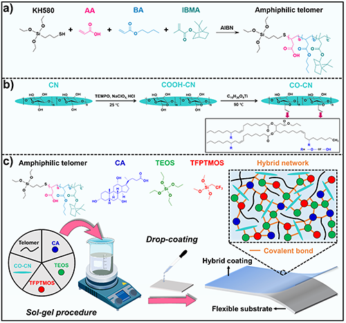
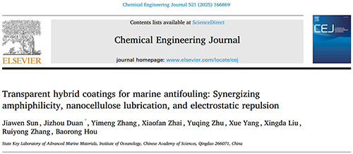
Fig. 1. Hybrid coating design. (A) Synthetic route of the amphiphilic telomer. (B) Surface modification route of CN. (C) Preparation process of the hybrid coating.
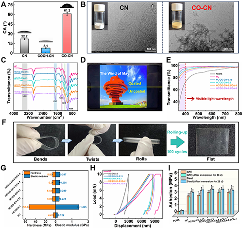
Fig. 2. Characterization of hybrid coatings. (A) Water contact angles of CN, COOH-CN, and CO-CN. (B) Digital photographs and TEM images of CN and CO-CN. (C) FTIR spectra of the hybrid coatings. (D) Photograph of HC/CO-CN-0.3/CA-3 coated on a PET substrate. (E) Transmittance spectra of the PDMS and hybrid coatings with a thickness of ≈100 μm. (F) Photographs of the HC/CO-CN-0.3/CA-3 coating and its deformations presented by bends, twists, and rolls. (G) Hardness and elastic modulus. (H) Load-displacement curves of the hybrid coatings. (I) Adhesion strength of each coating adhered to the GFE and steel before and after immersion in ASW for 28 days.
Fig. 3. Analysis of surface properties. (A) WCA and SFE of coatings. (B) AFM profiles of HC/CO-CN-0.3/CA-3 evaluated in amplitude modulation mode in air (left to right: 3D topography image (20 × 20 μm2) and Rq (nm), 2D topography image (20 × 20 μm2), and height profile across the red line). (C) Friction coefficient curves, and (D) friction coefficient values of hybrid coatings. (E) Schematic diagram of the lubrication mechanism of the hybrid coatings. (F) Self-cleaning performance of HC/CO-CN-0.3/CA-3. (G) Amount of BSA adsorbed on the different coatings. (H) Pseudobarnacle removal strength of the coatings.
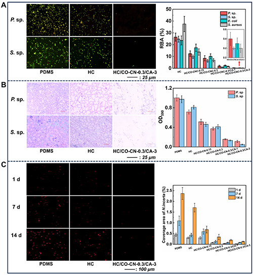
Fig. 4. Anti-biofouling performance tests. (A) Fluorescence images of P. sp., S. sp., E. coli, and S. aureus adhered to PDMS, HC and HC/CO-CN-0.3/CA-3 surface, relative bacteria adhesion (RBA) on different coatings. (B) P. sp. and S. sp. biofilms grown on PDMS, HC and HC/CO-CN-0.3/CA-3 surface stained with crystal violet, OD590 values against P. sp. and S. sp. on different coatings. (C) Fluorescence images of N. incerta adhered to PDMS, HC and HC/CO-CN-0.3/CA-3 surface after immersion in a diatom cell suspension for 1, 7, and 14 days, percent of the coverage area of N.incerta on different coatings.
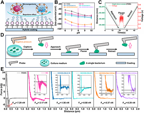
Fig. 5. Analysis of antifouling mechanism. (A) Schematic diagram showing the repulsive effect of electrostatic forces between the microorganisms and coating surfaces. (B) Zeta potential on each coating surface. (C) Voltage-time curve demonstrating the temporal evolution of voltage as a single bacterium P. sp. approached, contacted, and subsequently detached from the PDMS coating surface. (D) Simplified schematic diagram of measuring adhesion forces between a single bacterium and coating surface based on FluidFM-based SCFS. (E) Typical adhesion force (Fad)-distance curves between a single bacterium and coating surface. The adhesion force was calculated by quantifying the difference between the lowest point (red circle) in a specific adhesion force curve and the corresponding point where the adhesion force finally reached a relatively steady state with time.

Fig. 6. Marine field tests and high-throughput pyrosequencing results. (A) Images of different tested panels following immersion in Qingdao Sea for durations of 0, 30, 60, 120, and 180 days from December 2023 to June 2024. (B) Composition of microbial communities shown in their relative abundance at the class level; and (C) genus level based on 16S rRNA gene amplicon analysis.
论文信息:
Jiawen Sun, Jizhou Duan*, Yimeng Zhang, Xiaofan Zhai, Yuqing Zhu, Xue Yang, Xingda Liu, Ruiyong Zhang, Baorong Hou. Transparent hybrid coatings for marine antifouling: Synergizing amphiphilicity, nanocellulose lubrication, and electrostatic repulsion. Chemical Engineering Journal, 2025, 521, 166869. DOI: 10.1016/j.cej.2025.166869.
原文链接:https://doi.org/10.1016/j.cej.2025.166869
