
随着智能纺织和可穿戴电子设备的快速发展,储能单元不仅要具备更高的能量密度和安全性,还需要在弯曲、折叠等复杂形变条件下保持稳定工作。全固态锂金属电池因兼具高安全性和高能量密度潜力,被认为是下一代储能的重要方向。其中,复合固态电解质通过将无机陶瓷与聚合物相结合,兼顾离子传导、机械强度和界面适应性,是目前固态电池的重要电解质体系之一。然而,复合固态电解质中陶瓷与聚合物之间往往存在明显的界面不匹配,容易造成填料团聚、界面缺陷和Li?传输路径中断,制约其进一步发展。
近日,浙江理工大学纺织科学与工程学院(国际丝绸学院)胡毅教授团队针对这一问题,将纤维结构构筑与分子界面调控相结合,提出了一种分子桥介导的陶瓷–聚合物界面耦合策略。研究团队利用静电纺丝构建连续纳米纤维骨架,并引入PFDTES分子桥实现LLZTO陶瓷与PVDF-HFP聚合物之间的稳定界面耦合,成功制备出高性能复合固态电解质PLF-CSE,为高性能柔性固态储能器件提供了新的设计思路。
2026年9月8日,该成果以《Molecular Bridging of Ceramic–Polymer Interfaces Enables Fast Ion Transport and Long-Life Solid-State Lithium Metal Batteries》为题,在国际权威期刊 《Advanced Functional Materials》 上发表。论文第一作者为浙江理工大学纺织科学与工程学院(国际丝绸学院)博士研究生李德华,通讯作者为浙江理工大学博士生导师胡毅教授。
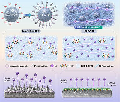
Figure 1. Schematic Illustration of PFDTES Molecular-Bridge Interfacial Regulation.
具体内容如下:
如图1所示,研究团队利用PFDTES构筑连接LLZTO陶瓷与PVDF-HFP聚合物的“分子桥”。该设计不仅能够改善陶瓷/聚合物界面相容性,减少填料团聚和界面缺陷,还能够调节局部Li+配位环境,促进Li+在不同组分之间连续迁移。同时,通过静电纺丝构筑连续纳米纤维网络,实现F-LLZTO在PVDF-HFP纤维中的均匀分布。连续纤维骨架既为复合电解质提供了良好的力学支撑,也为构建连续离子传输通道提供了结构基础,体现了纤维材料结构设计在固态电解质中的应用优势。
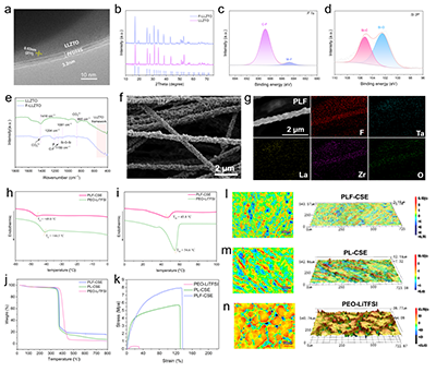
Figure 2. Interfacial construction and structural characterization of PLF-CSE. (a) High-resolution transmission electron microscopy (HRTEM) image of PFDTES-grafted F-LLZTO; (b) XRD patterns of LLZTO and F-LLZTO; (c) high-resolution F 1s XPS spectrum of F-LLZTO; (d) high-resolution Si 2p XPS spectrum of F-LLZTO; (e) FTIR spectra of LLZTO and F-LLZTO; (f) SEM image of electrospun PLF (F-LLZTO/PVDF-HFP) composite nanofibers; (g) SEM image of a single PLF composite nanofiber and the corresponding EDS elemental mappings; (h) DSC curves of PEO–LiTFSI and PLF-CSE electrolytes showing the glass-transition behavior; (i) DSC curves of PEO–LiTFSI and PLF-CSE electrolytes showing the melting behavior; (j) TGA curves of PEO–LiTFSI, PL-CSE, and PLF-CSE electrolytes; (k) stress–strain curves of PEO–LiTFSI, PL-CSE, and PLF-CSE electrolyte membranes; (l–n) 2D and 3D laser scanning confocal microscopy (LSCM) images of different electrolyte membrane surfaces: (l) PLF-CSE, (m) PL-CSE, and (n) PEO–LiTFSI.
如图2所示,结构表征进一步证实PFDTES成功修饰于LLZTO表面,并有效改善了陶瓷颗粒在PVDF-HFP纤维中的分散状态。静电纺丝形成的复合纤维保持连续交织的三维网络结构,为陶瓷功能组分提供了稳定载体。得益于纤维骨架和分子桥界面的协同作用,PLF-CSE不仅降低了PEO结晶程度,还显著提升了膜的力学性能,其极限拉伸强度达到7.9 MPa,同时保持135.6%的断裂伸长率,体现出良好的强韧协同特征。
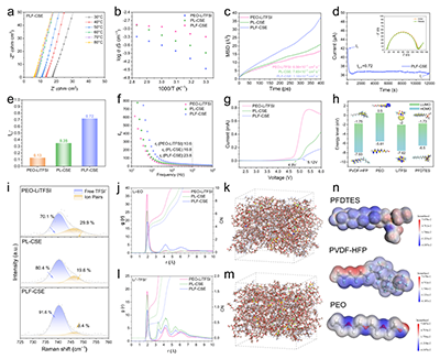
Figure 3. Electrochemical performance and Li+ transport mechanism of the PLF-CSE composite solid electrolyte. (a) EIS spectra of PLF-CSE at 30–80 °C; (b) Arrhenius plots of ionic conductivity for PEO–LiTFSI, PL-CSE, and PLF-CSE; (c) mean squared displacement (MSD) curves and corresponding Li+ diffusion coefficients of PEO–LiTFSI, PL-CSE, and PLF-CSE. (d) chronoamperometric curve of the Li|PLF-CSE|Li symmetric cell under a DC polarization voltage of 10 mV, with the inset showing the EIS spectra before and after polarization; (e) comparison of Li+ transference numbers of PEO–LiTFSI, PL-CSE, and PLF-CSE; (f) frequency-dependent dielectric constants of PEO–LiTFSI, PL-CSE, and PLF-CSE; (g) linear sweep voltammetry (LSV) curves of PEO–LiTFSI, PL-CSE, and PLF-CSE; (h) DFT-calculated HOMO/LUMO energy levels of PVDF-HFP, PEO, LiTFSI, and PFDTES; (i) Raman spectra in the range of 725–760 cm?1 for analyzing the dissociation state of TFSI? in different electrolyte systems; (j) radial distribution functions and coordination numbers of Li+–EO (ether oxygen in PEO) in PEO–LiTFSI, PL-CSE, and PLF-CSE obtained from MD simulations; (k) MD simulation structural snapshot of PLF-CSE; (l) radial distribution functions and coordination numbers of Li+–TFSI? in PEO–LiTFSI, PL-CSE, and PLF-CSE obtained from MD simulations (m) MD simulation structural snapshot of PL-CSE; (n) electrostatic potential (ESP) distributions of PFDTES, PVDF-HFP, and PEO molecules.
如图3所示,分子桥调控显著改善了PLF-CSE的离子传输性能。其在30 ℃下的离子电导率达到5.05 × 10?4 S·cm?1,Li+迁移数达到0.72,同时具有5.12 V的电化学稳定窗口。Raman测试和分子动力学模拟进一步表明,PFDTES能够削弱Li+与TFSI?及PEO醚氧之间的局部配位作用,使Li+处于更加活跃的配位交换环境中,从而促进其在连续纤维复合体系中的快速迁移。
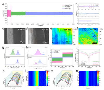
Figure 4. Molecular-bridge interfacial regulation of lithium metal interfacial stability and plating/stripping behavior. (a) Long-term galvanostatic lithium plating/stripping cycling performance of Li|PEO–LiTFSI|Li, Li|PL-CSE|Li, and Li|PLF-CSE|Li symmetric cells at 0.1 mA cm?2; (b) enlarged voltage profiles at different cycling stages; (c,d) cross-sectional SEM images of lithium metal anodes after cycling in Li|PLF-CSE|Li and Li|PL-CSE|Li symmetric cells; (e,f) LSCM 2D height maps of cycled lithium metal surfaces from Li|PLF-CSE|Li and Li|PL-CSE|Li symmetric cells; (g,h) high-resolution XPS spectra of cycled lithium metal surfaces: (g) F 1s and (h) N 1s; (i) voltage responses of different Li||Li symmetric cells under intermittent galvanostatic pulse polarization at 0.1 mA cm?2; (j) Tafel polarization curves of Li||Li symmetric cells with different electrolytes; (k,l) three-dimensional EIS evolution and corresponding DRT analysis of the Li|PL-CSE|Li symmetric cell during cycling; (m,n) three-dimensional EIS evolution and corresponding DRT analysis of the Li|PLF-CSE|Li symmetric cell during cycling.
如图4所示,PLF-CSE不仅提升了体相离子传输效率,也显著改善了锂金属界面稳定性。在0.1 mA·cm?2条件下,Li|PLF-CSE|Li对称电池能够稳定循环超过6000 h,明显优于对照体系。循环后的锂金属表面更加平整致密,同时形成了富含LiF和Li?N的稳定无机界面层,有助于均匀Li+通量、降低界面副反应并抑制不均匀锂沉积。
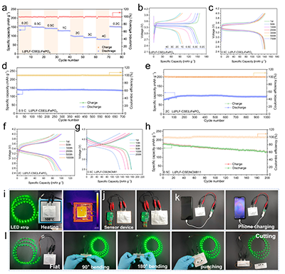
Figure 5. Solid-state full-cell performance and device-level application validation of PLF-CSE. (a) Rate performance of the LFP|PLF-CSE|Li solid-state full cell; (b) charge–discharge profiles of the LFP|PLF-CSE|Li solid-state full cell at different rates; (c) charge–discharge profiles of the LFP|PLF-CSE|Li solid-state full cell at selected cycles at 0.5 C; (d) long-term cycling performance of the LFP|PLF-CSE|Li solid-state full cell at 0.5 C; (e) long-term cycling performance of the LFP|PLF-CSE|Li solid-state full cell at 2 C; (f) charge–discharge profiles of the LFP|PLF-CSE|Li solid-state full cell at selected cycles at 2 C; (g) charge–discharge profiles of the NCM811|PLF-CSE|Li solid-state full cell at selected cycles at 0.5 C; (h) cycling performance of the NCM811|PLF-CSE|Li solid-state full cell at 0.5 C; (i) photographs of a PLF-CSE-based solid-state pouch cell powering an LED strip under normal operation and heating at 100 °C, together with the corresponding infrared thermal image; (j) photograph of the PLF-CSE-based solid-state pouch cell powering a sensor module; (k) photograph of the PLF-CSE-based solid-state pouch cell charging a mobile phone; (l) photographs of the PLF-CSE-based solid-state pouch cell powering an LED strip under flat, 90° bending, 180° bending, hole-punching, and cutting conditions.
如图5所示,PLF-CSE在固态全电池中表现出良好的长循环和高倍率性能。LFP|PLF-CSE|Li电池在0.5 C下循环700圈后容量保持率超过95%,在2 C高倍率下循环1000圈后仍保持92.9%的容量。进一步组装的固态软包电池能够在100 ℃环境以及90°、180°弯折等状态下保持稳定供电,并可驱动传感器和手机,展现出良好的柔性和器件适应能力。
总之,本研究通过PFDTES分子桥界面调控与静电纺丝纤维网络构筑相结合,有效改善了陶瓷–聚合物界面相容性和Li+传输连续性。所得PLF-CSE兼具良好的离子传导、力学稳定性和锂金属界面稳定性,实现了超过6000 h的Li|Li稳定循环以及2 C下1000圈的全电池长循环性能。该研究为复合固态电解质的界面设计提供了新的思路,也进一步拓展了纤维材料和静电纺丝技术在先进储能领域中的应用。
本研究得到了国家自然科学基金(22678533)和浙江理工大学嵊州创新研究院基金(SYY2024C000008)的支持。
原文链接:https://doi.org/10.1002/adfm.78321
